Power + M12 Wiring Guide
This guide explains how to properly power the OV80i camera using an M12 12-pin A-coded connector — either through a direct power supply connection or a terminal block adapter.
Power Requirements
- Voltage Input: 24V DC ±10%
- Power Draw: ~10W typical
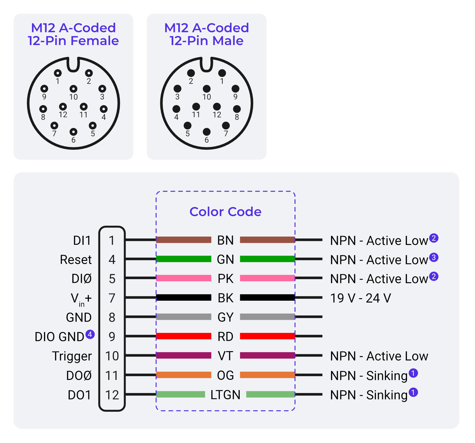
- Connector: M12 12-pin A-coded (Male on camera)
Power Pin Mapping (Per Documentation)
| Pin # | Function |
|---|---|
| 7 | +24V (Vin+) |
| 8 | GND |
Option 1: M12 Cable to Power Supply
Use a third-party or Advantech-compatible M12 12-pin pigtail cable.
Steps:
- Identify wires for Pin 7 (usually BK) → connect to +24V.
- Identify wires for Pin 8 (often GY) → connect to GND.
- Connect securely to a 24V regulated DC power supply.
- Power on and confirm that the Power LED (rightmost) is green.
Option 2: M12 to Terminal Block Adapter
Used for easy bench testing or modular installs.
- Use a breakout board that exposes all 12 pins.
- Connect +24V to Pin 7.
- Connect GND to Pin 8.
- Use remaining terminals for I/O, triggers, and outputs if needed.
Confirming Power Status
- ✅ Power LED = Green → System OK
- ❌ Power LED = Red → Undervoltage, wrong polarity, or wiring fault
- ✅ Ethernet LED = Orange → Network link active
- ❌ Ethernet LED = Off → No network link
Safety Reminders
- Always power off before rewiring.
- Use only regulated industrial 24V power sources.
- Double-check polarity before connecting.
- If in doubt, measure voltage at M12 cable pins before plug-in.